Day 51: Understanding the OSI Model
Note: I was very rushed to edit this, this will turn into the ultimate OSI model guide so please be patient for now while I improve this guide. Thank you!
The Open Systems Interconnection model (OSI model) is a conceptual model that characterises and standardises the communication functions of a telecommunication or computing system without regard to its underlying internal structure and technology. Its goal is the interoperability of diverse communication systems with standard protocols. The model partitions a communication system into abstraction layers. The original version of the model defined seven layers.

The Physical Layer
The physical layer transmits raw bits over a communication channel, this layer needs to make sure that when one side sends a 1 bit it is received by the other side as a 1 bit, not as a 0 bit.
Typical Design Issues
- What electrical signals should be used to represent a 1 and a 0
- How many nanoseconds a bit lasts, whether transmission may proceed simultaneously in both directionsH
- How the initial connection is established
- How it is torn down when both sides are finished
- How many pins the network connector has, and what each pin is used for.
These design issues largely deal with mechanical, electrical, and timing interfaces, as well as the physical transmission medium, which lies below the physical layer.
Physical Layer Duties
- Modulates the process of converting a signal from one form to another so that it can be physically transmitted over a communication channel
- Bit-by-bit delivery
- Line coding, which allows data to be sent by hardware devices that are optimised for digital communications that may have discreet timing on the transmission link
- Bit synchronisation for synchronous serial communications
- Start-stop signalling and flow control in asynchronous serial communication
- Circuit switching and multiplexing hardware control of multiplexed digital signals
- Carrier sensing and collision detection, whereby the physical layer detects carrier availability and avoids the congestion problems caused by undeliverable packets
- Signal equalisation to ensure reliable connections and facilitate multiplexing
- Forward error correction/channel coding such as error correction code
- Bit interleaving to improve error correction
- Auto-negotiation
- Transmission mode control
Example Protocols that use Physical Layer
- Digital Subscriber Line
- Integrated Services Digital Network
- Infrared Data Association
- Universal Serial Bus
- Bluetooth
- Controller Area Network
- Ethernet
The Data Link Layer
The main task of the data link layer is to transform a raw transmission facility into a line that appears free of undetected transmission errors. It does so by masking the real errors so the network layer does not see them. It accomplishes this task by having the sender break up the input data into data frames (typically a few hundred or a few thousand bytes) and transmit the frames sequentially. If the service is reliable, the receiver confirms correct receipt of each frame by sending back an acknowledgement frame. Another issue that arises in the data link layer (and most of the higher layers as well) is how to keep a fast transmitter from drowning a slow receiver in data. Some traffic regulation mechanism may be needed to let the transmitter know when the receiver can accept more data. Broadcast networks have an additional issue in the data link layer: how to control access to the shared channel. A special sublayer of the data link layer, the medium access control sublayer, deals with this problem.
The data link layer’s first sublayer is the media access control (MAC) layer. It is used for source and destination addresses. The MAC layer allows the data link layer to provide the best data transmission vehicle and manage data flow control.
The data link layer’s second sublayer is the logical link control. It manages error checking and data flow over a network.
Data Link Layer Duties
- It handles problems that occur as a result of bit transmission errors.
- It ensures data flows at a pace that doesn’t overwhelm sending and receiving devices.
- It permits the transmission of data to Layer 3, the network layer, where it is addressed and routed.
Data Link Layer — Physical Addressing
Physical addressing is different from network addressing. Network addresses differentiate between nodes or devices in a network, allowing traffic to be routed or switched through the network. In contrast, physical addressing identifies devices at the link-layer level, differentiating between individual devices on the same physical medium. The primary form of physical addressing is the media access control (MAC) address.
Data Link Layer — Network Topology
Network topology specifications identify how devices are linked in a network. Some media allow devices to be connected by a bus topology, while others require a ring topology. The bus topology is used by Ethernet technologies, which are supported on Juniper Networks devices.
Data Link Layer — Error Notification
The Data Link Layer provides error notifications that alert higher layer protocols that an error has occurred on the physical link. Examples of link-level errors include the loss of a signal, the loss of a clocking signal across serial connections, or the loss of the remote endpoint on a T1 or T3 link.
Data Link Layer — Frame Sequencing
The frame sequencing capabilities of the Data Link Layer allow frames that are transmitted out of sequence to be reordered on the receiving end of a transmission. The integrity of the packet can then be verified by means of the bits in the Layer 2 header, which is transmitted along with the data payload.
Data Link Layer — Flow Control
Flow control within the Data Link Layer allows receiving devices on a link to detect congestion and notify their upstream and downstream neighbors. The neighbour devices relay the congestion information to their higher layer protocols so that the flow of traffic can be altered or rerouted.
Data Link Layer — Data Link Sublayers
The Data Link Layer is divided into two sublayers: logical link control (LLC) and media access control (MAC). The LLC sublayer manages communications between devices over a single link of a network. This sublayer supports fields in link-layer frames that enable multiple higher layer protocols to share a single physical link.
The MAC sublayer governs protocol access to the physical network medium. Through the MAC addresses that are typically assigned to all ports on a device, multiple devices on the same physical link can uniquely identify one another at the Data Link Layer. MAC addresses are used in addition to the network addresses that are typically configured manually on ports within a network.
Data Link Layer — MAC Addressing
A MAC address is the serial number permanently stored in a device adapter to uniquely identify the device. MAC addresses operate at the Data Link Layer, while IP addresses operate at the Network Layer. The IP address of a device can change as the device is moved around a network to different IP subnets, but the MAC address remains the same, because it is physically tied to the device.
Within an IP network, devices match each MAC address to its corresponding configured IP address by means of the Address Resolution Protocol (ARP). ARP maintains a table with a mapping for each MAC address in the network.
Most Layer 2 networks use one of three primary numbering spaces — MAC-48, EUI-48 (extended unique identifier), and EUI-64 — which are all globally unique. MAC-48 and EUI-48 spaces each use 48-bit addresses, and EUI-64 spaces use a 64-bit addresses, but all three use the same numbering format. MAC-48 addresses identify network hardware, and EUI-48 addresses identify other devices and software.
The Ethernet and ATM technologies supported on devices use the MAC-48 address space. IPv6 uses the EUI-64 address space.
MAC-48 addresses are the most commonly used MAC addresses in most networks. These addresses are 12-digit hexadecimal numbers (48 bits in length) that typically appear in one of the following formats:
- MM:MM:MM:SS:SS:SS
- MM-MM-MM-SS-SS-SS
The first three octets (MM:MM:MM or MM-MM-MM) are the ID number of the hardware manufacturer. Manufacturer ID numbers are assigned by the Institute of Electrical and Electronics Engineers (IEEE). The last three octets (SS:SS:SSor SS-SS-SS) make up the serial number for the device, which is assigned by the manufacturer. For example, an Ethernet interface card might have a MAC address of 00:05:85:c1:a6:a0.
Link Layer Protocols
The link layer in the TCP/IP model is a descriptive realm of networking protocols that operate only on the local network segment (link) that a host is connected to. Such protocol packets are not routed to other networks. The link layer includes the protocols that define communication between local (on-link) network nodes which fulfil the purpose of maintaining link states between the local nodes, such as the local network topology, and that usually use protocols that are based on the framing of packets specific to the link types.
The core protocols specified by the Internet Engineering Task Force (IETF) in this layer are the Address Resolution Protocol (ARP), the Reverse Address Resolution Protocol (RARP), and the Neighbour Discovery Protocol (NDP), which is a facility delivering similar functionality as ARP for IPv6. Since the advent of IPv6, Open Shortest Path First (OSPF) is considered to operate on the link level as well, although the IPv4 version of the protocol was considered at the Internet layer.[citation needed]
IS-IS (RFC 1142) is another link-state routing protocol that fits into this layer when considering TCP/IP model, however it was developed within the OSI reference stack, where it is a Layer 2 protocol. It is not an Internet standard.
The Network Layer
The network layer controls the operation of the subnet. A key design issue is determining how packets are routed from source to destination. Routes can be based on static tables that are ‘‘wired into’’ the network and rarely changed, or more often they can be updated automatically to avoid failed components. They can also be determined at the start of each conversation, for example, a terminal session, such as a login to a remote machine. Finally, they can be highly dynamic, being determined anew for each packet to reflect the current network load. If too many packets are present in the subnet at the same time, they will get in one another’s way, forming bottlenecks. Handling congestion is also a responsibility of the network layer, in conjunction with higher layers that adapt the load they place on the network. More generally, the quality of service provided (delay, transit time, jitter, etc.) is also a network layer issue. When a packet has to travel from one network to another to get to its destination, many problems can arise. The addressing used by the second network may be different from that used by the first one. The second one may not accept the packet at all because it is too large. The protocols may differ, and so on. It is up to the network layer to overcome all these problems to allow heterogeneous networks to be interconnected. In broadcast networks, the routing problem is simple, so the network layer is often thin or even nonexistent.
The network layer is the third level of the Open Systems Interconnection Model (OSI Model) and the layer that provides data routing paths for network communication. Data is transferred in the form of packets via logical network paths in an ordered format controlled by the network layer.
Logical connection setup, data forwarding, routing and delivery error reporting are the network layer’s primary responsibilities.
Example Protocols that use Network Layer
Network protocols provide what are called “link services”. These protocols handle addressing and routing information, error checking, and retransmission requests. Network protocols also define rules for communicating in a particular networking environment such as Ethernet or Token Ring.
IP — This is short for Internet Protocol which works at the OSI network layer and is a routed protocol for forwarding layer 3 packets.
IPX — NetWare’s protocol for packet forwarding and routing.
The Transport Layer
The basic function of the transport layer is to accept data from above it, split it up into smaller units if need be, pass these to the network layer, and ensure that the pieces all arrive correctly at the other end. Furthermore, all this must be done efficiently and in a way that isolates the upper layers from the inevitable changes in the hardware technology over the course of time. The transport layer also determines what type of service to provide to the session layer, and, ultimately, to the users of the network. The most popular type of transport connection is an error-free point-to-point channel that delivers messages or bytes in the order in which they were sent. However, other possible kinds of transport service exist, such as the transporting of isolated messages with no guarantee about the order of delivery, and the broadcasting of messages to multiple destinations. The type of service is determined when the connection is established. (As an aside, an error-free channel is completely impossible to achieve; what people really mean by this term is that the error rate is low enough to ignore in practice.) The transport layer is a true end-to-end layer; it carries data all the way from the source to the destination. In other words, a program on the source machine carries on a conversation with a similar program on the destination machine, using the message headers and control messages. In the lower layers, each protocols is between a machine and its immediate neighbours, and not between the ultimate source and destination machines, which may be separated by many routers.
Services
Transport layer services are conveyed to an application via a programming interface to the transport layer protocols. The services may include the following features:
- Connection-oriented communication: It is normally easier for an application to interpret a connection as a data stream rather than having to deal with the underlying connection-less models, such as the datagram model of the User Datagram Protocol (UDP) and of the Internet Protocol (IP).
- Same order delivery: The network layer doesn’t generally guarantee that packets of data will arrive in the same order that they were sent, but often this is a desirable feature. This is usually done through the use of segment numbering, with the receiver passing them to the application in order. This can cause head-of-line blocking.
- Reliability: Packets may be lost during transport due to network congestion and errors. By means of an error detection code, such as a checksum, the transport protocol may check that the data is not corrupted, and verify correct receipt by sending an ACK or NACK message to the sender. Automatic repeat request schemes may be used to retransmit lost or corrupted data.
- Flow control: The rate of data transmission between two nodes must sometimes be managed to prevent a fast sender from transmitting more data than can be supported by the receiving data buffer, causing a buffer overrun. This can also be used to improve efficiency by reducing buffer underrun.
- Congestion avoidance: Congestion control can control traffic entry into a telecommunications network, so as to avoid congestive collapse by attempting to avoid oversubscription of any of the processing or link capabilities of the intermediate nodes and networks and taking resource reducing steps, such as reducing the rate of sending packets. For example, automatic repeat requests may keep the network in a congested state; this situation can be avoided by adding congestion avoidance to the flow control, including slow-start. This keeps the bandwidth consumption at a low level in the beginning of the transmission, or after packet retransmission.
- Multiplexing: Ports can provide multiple endpoints on a single node. For example, the name on a postal address is a kind of multiplexing, and distinguishes between different recipients of the same location. Computer applications will each listen for information on their own ports, which enables the use of more than one network service at the same time. It is part of the transport layer in the TCP/IP model, but of the session layer in the OSI model.
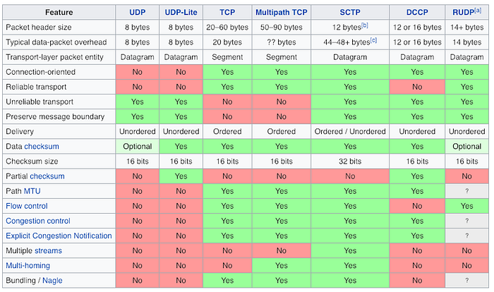
Transport Layer Protocols
This list shows some protocols that are commonly placed in the transport layers of the Internet protocol suite, the OSI protocol suite, NetWare’s IPX/SPX, AppleTalk, and Fibre Channel.
- ATP, AppleTalk Transaction Protocol
- CUDP, Cyclic UDP
- DCCP, Datagram Congestion Control Protocol
- FCP, Fibre Channel Protocol
- IL, IL Protocol
- MPTCP, Multipath TCP
- RDP, Reliable Data Protocol
- RUDP, Reliable User Datagram Protocol
- SCTP, Stream Control Transmission Protocol
- SPX, Sequenced Packet Exchange
- SST, Structured Stream Transport
- TCP, Transmission Control Protocol
- UDP, User Datagram Protocol
- UDP-Lite
- µTP, Micro Transport Protocol
The Session Layer
The session layer allows users on different machines to establish sessions between them. Sessions offer various services, including dialog control (keeping track of whose turn it is to transmit), token management (preventing two parties from attempting the same critical operation simultaneously), and synchronisation (checkpointing long transmissions to allow them to pick up from where they left off in the event of a crash and subsequent recovery).
Session Layer Protocols
- ADSP, AppleTalk Data Stream Protocol
- ASP, AppleTalk Session Protocol
- H.245, Call Control Protocol for Multimedia Communication
- ISO-SP, OSI session-layer protocol (X.225, ISO 8327)
- iSNS, Internet Storage Name Service
- L2F, Layer 2 Forwarding Protocol
- L2TP, Layer 2 Tunneling Protocol
- NetBIOS, Network Basic Input Output System
- PAP, Password Authentication Protocol
- PPTP, Point-to-Point Tunnelling Protocol
- RPC, Remote Procedure Call Protocol
- RTCP, Real-time Transport Control Protocol
- SMPP, Short Message Peer-to-Peer
- SCP, Session Control Protocol
- SOCKS, the SOCKS internet protocol, see Internet socket
- ZIP, Zone Information Protocol
- SDP, Sockets Direct Protocol
The Presentation Layer
Unlike the lower layers, which are mostly concerned with moving bits around, the presentation layer is concerned with the syntax and semantics of the information transmitted. In order to make it possible for computers with different internal data representations to communicate, the data structures to be exchanged can be defined in an abstract way, along with a standard encoding to be used ‘‘on the wire.’’ The presentation layer manages these abstract data structures and allows higher-level data structures (e.g., banking records) to be defined and exchanged.
Services
The Application Layer
The application layer contains a variety of protocols that are commonly needed by users. One widely used application protocol is HTTP (HyperText Transfer Protocol), which is the basis for the World Wide Web. When a browser wants a Web page, it sends the name of the page it wants to the server hosting the page using HTTP. The server then sends the page back. Other application protocols are used for file transfer, electronic mail, and network news.
Protocols
- 9P, Plan 9 from Bell Labs distributed file system protocol
- AFP, Apple Filing Protocol
- APPC, Advanced Program-to-Program Communication
- AMQP, Advanced Message Queuing Protocol
- Atom Publishing Protocol
- BEEP, Block Extensible Exchange Protocol
- Bitcoin
- BitTorrent
- CFDP, Coherent File Distribution Protocol
- CoAP, Constrained Application Protocol
- DDS, Data Distribution Service
- DeviceNet
- eDonkey
- ENRP, Endpoint Handlespace Redundancy Protocol
- FastTrack (KaZaa, Grokster, iMesh)
- Finger, User Information Protocol
- Freenet
- FTAM, File Transfer Access and Management
- Gopher, Gopher protocol
- HL7, Health Level Seven
- HTTP, HyperText Transfer Protocol
- H.323, Packet-Based Multimedia Communications System
- IMAP, Internet Message Access Protocol
- IRCP, Internet Relay Chat Protocol
- IPFS, InterPlanetary File System
- Kademlia
- LDAP, Lightweight Directory Access Protocol
- LPD, Line Printer Daemon Protocol
- MIME (S-MIME), Multipurpose Internet Mail Extensions and Secure MIME
- Modbus
- MQTT Protocol
- Netconf
- NFS, Network File System
- NIS, Network Information Service
- NNTP, Network News Transfer Protocol
- NTCIP, National Transportation Communications for Intelligent Transportation System Protocol
- NTP, Network Time Protocol
- OSCAR, AOL Instant Messenger Protocol
- POP, Post Office Protocol
- PNRP, Peer Name Resolution Protocol
- RDP, Remote Desktop Protocol
- RELP, Reliable Event Logging Protocol
- Rlogin, Remote Login in UNIX Systems
- RPC, Remote Procedure Call
- RTMP, Real Time Messaging Protocol
- RTP, Real-time Transport Protocol
- RTPS, Real Time Publish Subscribe
- RTSP, Real Time Streaming Protocol
- SAP, Session Announcement Protocol
- SDP, Session Description Protocol
- SIP, Session Initiation Protocol
- SLP, Service Location Protocol
- SMB, Server Message Block
- SMTP, Simple Mail Transfer Protocol
- SNTP, Simple Network Time Protocol
- SSH, Secure Shell
- SSMS, Secure SMS Messaging Protocol
- TCAP, Transaction Capabilities Application Part
- TDS, Tabular Data Stream
- Tor (anonymity network)
- Tox
- TSP, Time Stamp Protocol
- VTP, Virtual Terminal Protocol
- Whois (and RWhois), Remote Directory Access Protocol
- WebDAV
- X.400, Message Handling Service Protocol
- X.500, Directory Access Protocol (DAP)
- XMPP, Extensible Messaging and Presence Protocol
Main source:
